Lecture12. About Gazebo - 2
Gazebo Sensor Plugin
Description 예시를 통해 URDF에 대해 습득하였다면, 이제 Gazebo에 로봇을 등장시키고, 이동, 센싱을 구현할 차례입니다. sensor stick을 통해 실습을 진행해보고, fusionbot도 함께 분석해 보겠습니다.
다뤄볼 센서들은 다음과 같습니다.
- Mono Camera
- Depth Camera
- 2D Lidar
- 3D Lidar
미리 말하자면 sensor plugin을 사용하는 기본 방법만 알면 gazebo_ros pkg wiki를 통해 얼마든지 응용이 가능합니다. 하지만 적어도 한번은 직접 plugin을 적용해보시기 바랍니다.
⇒ https://github.com/ros-simulation/gazebo_ros_pkgs/wiki
Sensor Plugin 추가 절차
다음은 일반적으로 제가 Gazebo Model에 센서를 연동할 때 적용하는 절차입니다.
- 센서가 부착될 link/joint 추가
- 기본 plugin xml 연동
- plugin parameter 수정
- Gazebo를 통해 동작 검증
⇒ 다시 2로 반복
basic_stick을 통해 카메라 센서들을, fusionbot을 통해 나머지를 실습해봅시다!!
- 센서가 부착될 link/joint 추가
⇒ link가 하나 추가되면 필연적으로 joint도 추가됩니다. 이를 기본 로봇 xacro에 반영합니다.
  <link name="camera_rgb_frame" />
  <joint name="camera_rgb_joint" type="fixed">
    <origin rpy="0 0 0" xyz="0 0.022 0" />
    <parent link="camera_link" />
    <child link="camera_rgb_frame" />
  </joint>
  <link name="camera_rgb_optical_frame" />
  <joint name="camera_rgb_optical_joint" type="fixed">
    <origin rpy="-1.57079632679 0 -1.57079632679" xyz="0 0 0" />
    <parent link="camera_rgb_frame" />
    <child link="camera_rgb_optical_frame" />
  </joint>
  <link name="camera_depth_frame" />
  <joint name="camera_depth_joint" type="fixed">
    <origin rpy="0 0 0" xyz="0 0.049 0" />
    <parent link="camera_link" />
    <child link="camera_depth_frame" />
  </joint>
  <link name="camera_depth_optical_frame" />
  <joint name="camera_depth_optical_joint" type="fixed">
    <origin rpy="-1.57079632679 0 -1.57079632679" xyz="0 0 0" />
    <parent link="camera_depth_frame" />
    <child link="camera_depth_optical_frame" />
  </joint>
- 기본 plugin xml 연동
⇒ 앞서 제시드린 gazebo_ros pkg wiki 예시를 참고하여 원하는 link에 센서 속성을 부여합니다. 지금은 Mono Camera를 부착해보겠습니다.
<gazebo reference="camera_rgb_frame">
    <sensor type="camera" name="rgb_cam">
      <update_rate>60</update_rate>
      <visualize>true</visualize>
      <always_on>1</always_on>
      <camera name="head">
        <horizontal_fov>1.3962634</horizontal_fov>
        <image>
          <width>1280</width>
          <height>720</height>
          <format>R8G8B8</format>
          <!-- <format>B8G8R8</format> -->
        </image>
        <clip>
          <near>0.02</near>
          <far>300</far>
        </clip>
        <noise>
          <type>gaussian</type>
          <mean>0.0</mean>
          <stddev>0.007</stddev>
        </noise>
      </camera>
      <plugin name="camera_controller" filename="libgazebo_ros_camera.so">
        <ros>
          <namespace>rgb_cam</namespace>
          <remapping>image_raw:=image_raw</remapping>
          <remapping>camera_info:=camera_info</remapping>
        </ros>
        <!-- camera_name>omit so it defaults to sensor name</camera_name-->
        <!-- <frame_name>omit so it defaults to link name</frame_name> -->
        <camera_name>front_camera</camera_name>
        <frame_name>camera_rgb_frame</frame_name>
        <hack_baseline>0.07</hack_baseline>
      </plugin>
    </sensor>
  </gazebo>
- Mono Camera plugin의 매개변수들은 다음과 같습니다.
이들을 여러분의 목적에 맞게 수정한 뒤, gazebo에서 실행하여 검증을 합니다.
| Parameter | Description |
|---|---|
| gazebo reference | camera가 장착되는 link |
| update_rate | data publish rate |
| visualize | 시각화 옵션 |
| horizontal_fov | 카메라의 화각 |
| image | 화질, 포맷 옵션 |
| noise | 센서 노이즈 |
| remapping | topic 이름 재설정 |
| camera_name | topic의 namespace가 됩니다. |
| frame_name | camera가 장착되는 link |
| hack_baseline | stereo camera 사용 시 - 카메라 사이 거리 |
| namespace | 동일 센서가 여러개 있을 시 namespace를 통해 구분할 수 있습니다. |
- Gazebo를 통해 검증하기 위해서, 일반 Gazebo가 아닌, gazebo_ros를 사용해야 합니다. 그래야 센서 데이터들이 topic publish 되기 때문입니다. 따라서 launch file 수정 후 실행의 절차를 반복합니다.
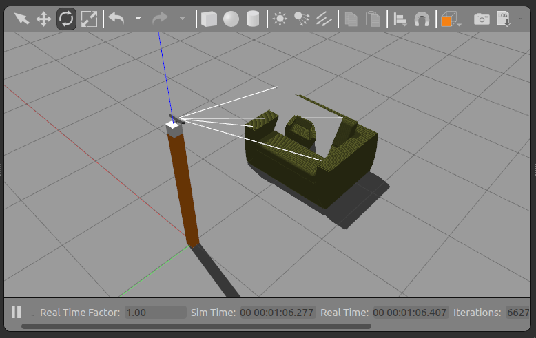
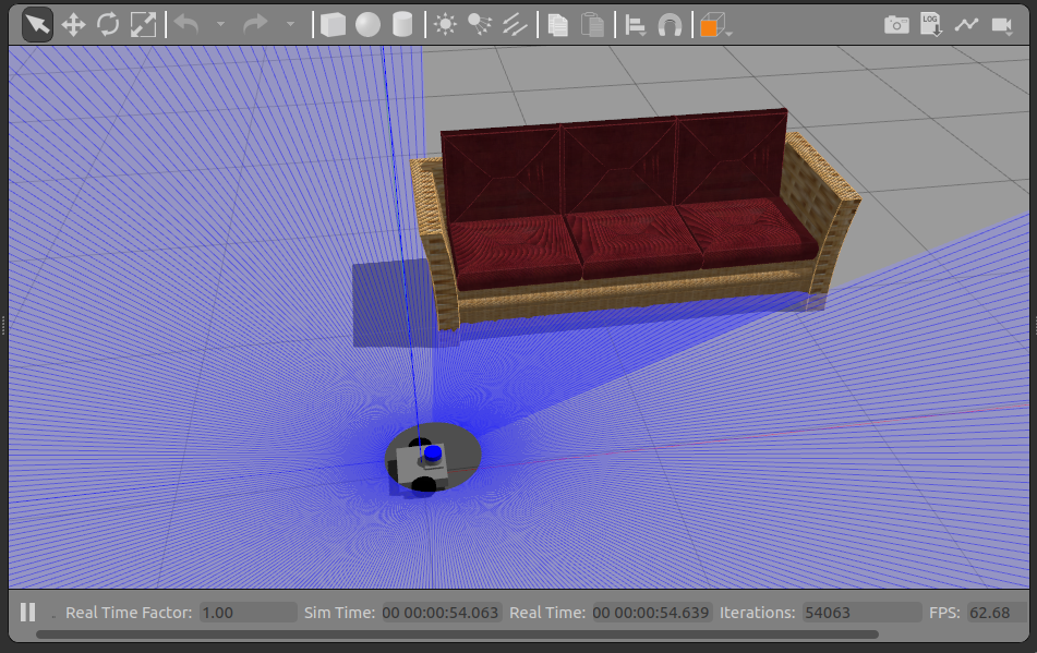
gazebo 실행 후 3DGEMS Model을 등장시켜 rviz2로 확인해보겠습니다.
ros2 launch basic_stick sensor_stick.launch.py
- Gazebo 연동 후 rqt, topic echo, rviz2, tf2 tree 등 지금까지 배운 모든 기능들을 사용해 검증하고, 디버깅합니다.
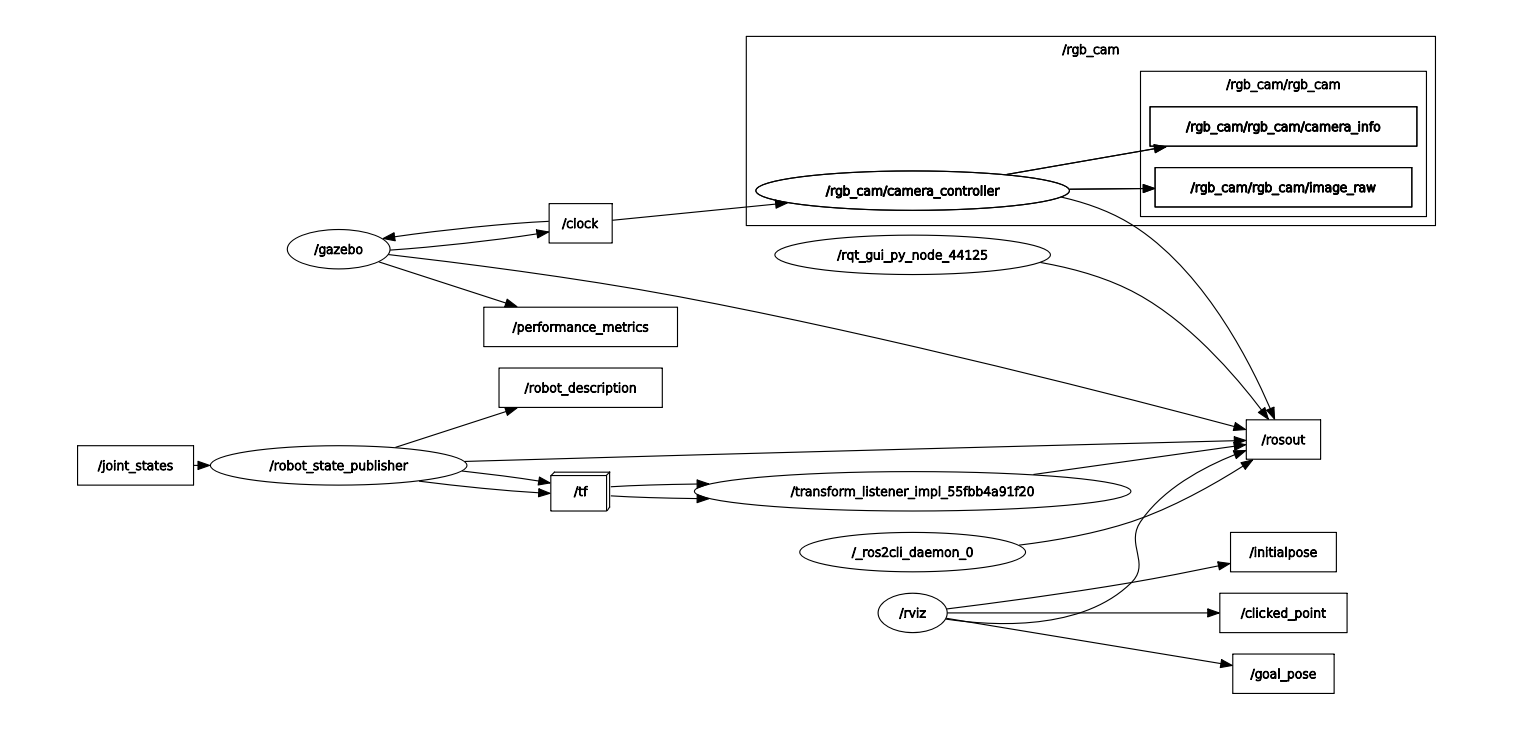
위 과정은 반복되므로, 센서 plugin 예시와 매개변수들을 위주로 살펴보겠습니다.
Depth Camera
⇒ Depth Camera 사용 시 주의해야 할 점이 있습니다. Depth Camera의 좌표계가 ROS 2 좌표계와 일치하지 않아 해당 joint angle을 통해 offset해야 합니다.
<link name="camera_rgb_optical_frame" />
<joint name="camera_rgb_optical_joint" type="fixed">
  <origin rpy="-1.57079632679 0 -1.57079632679" xyz="0 0 0" />
  <parent link="camera_rgb_frame" />
  <child link="camera_rgb_optical_frame" />
</joint>
- Depth Camera Parameter는 Mono Camera와 차이나는 부분을 살펴봅시다.
<gazebo reference="depth_camera_link">
  <sensor name="front_depth_camera" type="depth">
    ...
    <plugin filename="libgazebo_ros_camera.so" name="camera_controller">
      <ros>
        <!-- <namespace>custom_ns</namespace> -->
        <remapping>front_depth_camera/image_raw:=front_depth_camera/image_raw</remapping>
        <remapping>front_depth_camera/image_depth:=front_depth_camera/image_depth</remapping>
        <remapping>front_depth_camera/camera_info:=front_depth_camera/camera_info</remapping>
        <remapping>front_depth_camera/camera_info_depth:=front_depth_camera/camera_info_depth</remapping>
        <remapping>front_depth_camera/points:=front_depth_camera/points</remapping>
      </ros>

      <camera_name>front_depth_camera</camera_name>
      <frame_name>depth_camera_optical_link</frame_name>

      <hack_baseline>0.07</hack_baseline>

      <min_depth>0.001</min_depth>
      <max_depth>300.0</max_depth>
    </plugin>
  </sensor>
</gazebo>
| Parameter | Description |
|---|---|
| type=“depth” | |
| min_depth, max_depth | depth 최소, 최대 탐지거리 |
| image_depth | depth image topic이며, |
| camera_info_depth | depth camera의 정보를 담고 있는 topic입니다. |
| points | pointcloud data topic으로 XYZ와 RGB가 결합된 데이터를 얻게 됩니다. |
- xacro 파일 변경 후 Gazebo 예제 실행
sensor_stick.xacro의 line 13을 보면 다른 plugin들을 사용하는 추가 xacro file들을 나눠둔 것을 확인할 수 있습니다. sensor_stick_mono ⇒ sensor_stick_depth로 토글링한 뒤 다시 launch 해봅시다.
ros2 launch basic_stick sensor_stick.launch.py
다음으로 2D/3D 라이다 데이터를 연동해봅시다. 라이다는 바퀴를 가진 fusionbot으로 실습해 보겠습니다.
2D lidar plugin
<gazebo reference="lidar">
  <sensor name="lidar" type="ray">
    <pose>0 0 0 0 0 0</pose>
    <always_on>1</always_on>
    <visualize>1</visualize>
    <update_rate>10</update_rate>
    <ray>
      <scan>
        <horizontal>
          <samples>360</samples>
          <resolution>1.000000</resolution>
          <min_angle>-3.14159</min_angle>
          <max_angle>3.14159</max_angle>
        </horizontal>
      </scan>
      <range>
        <min>0.2</min>
        <max>10.0</max>
        <resolution>0.05</resolution>
      </range>
      <noise>
        <type>gaussian</type>
        <mean>0.0</mean>
        <stddev>0.01</stddev>
      </noise>
    </ray>
    <plugin filename="libgazebo_ros_ray_sensor.so" name="scan">
      <ros>
        <remapping>~/out:=scan</remapping>
      </ros>
      <output_type>sensor_msgs/LaserScan</output_type>
      <frame_name>lidar</frame_name>
    </plugin>
  </sensor>
</gazebo>
| Parameter | Description |
|---|---|
| type=“ray” | |
| samples | 라이다의 샘플 수를 지정합니다. 지금은 360개의 point를 각 1도씩 매핑해서 360도를 스캔하게 됩니다. |
| resolution | 스캔 해상도로 단위는 각도입니다. |
| min_angle / max_angle | 최대, 최소 각도이며 지금은 -180 ~ 180 즉 360도를 스캔합니다. |
| range | 탐지거리의 범위, 해상도를 정의합니다. |
| scan | 라이다의 스캔 결과는 기본적으로 scan이라는 topic으로 publish 됩니다. |
| output_type | ROS 2에서 사용하는 2D 라이다 데이터로 기본은 sensor_msgs/msg/LaserScan입니다. |
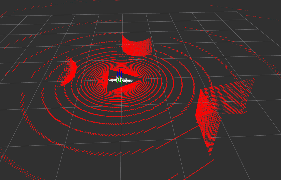
- 예제 실행
ros2 launch fusionbot_description sensor_gz.launch.py
3D Lidar plugin
⇒ 2D lidar와 plugin은 같지만, vertical이라는 속성이 추가됩니다.
이 센서는 연산량이 많아 gpu 버전을 별도로 제공하고 있습니다.
<!-- Gazebo requires the velodyne_gazebo_plugins package -->
<gazebo reference="velodyne">
  <sensor type="gpu_ray" name="block_laser_sensor">
    <ray>
      <scan>
        <horizontal>
          <samples>1200</samples>
          <resolution>1</resolution>
          <min_angle>-3.141592653589793</min_angle>
          <max_angle>3.141592653589793</max_angle>
        </horizontal>
        <vertical>
          <samples>64</samples>
          <resolution>1</resolution>
          <min_angle>-0.436322083</min_angle>
          <max_angle>0.2617993877991494</max_angle>
        </vertical>
      </scan>
      <range>
        <min>0.3</min>
        <max>201.0</max>
        <resolution>0.001</resolution>
      </range>
      <!-- Using gazebo's noise instead of plugin's -->
      <noise>
        <type>gaussian</type>
        <mean>0.0</mean>
        <stddev>0.0</stddev>
      </noise>
    </ray>
    <!-- Using gazebo's update rate instead of plugin's -->
    <update_rate>30</update_rate>
    <plugin name="gazebo_ros_block_laser_controller" filename="libgazebo_ros_ray_sensor.so">
      <!-- Change namespace and output topic so published topic is /rrbot/laser/pointcloud -->
      <ros>
        <!-- <namespace>/rrbot/laser</namespace> -->
        <remapping>~/out:=pointcloud</remapping>
      </ros>
      <!-- Set output to sensor_msgs/PointCloud to get same output type as gazebo_ros_block_laser -->
      <output_type>sensor_msgs/PointCloud2</output_type>
      <!-- <frame_name> ommited, will default to block_laser_link -->

      <!-- min_intensity instead of hokuyoMinIntensity -->
      <min_intensity>100.0</min_intensity>
    </plugin>
  </sensor>
</gazebo>
| Parameter | Description |
|---|---|
| type=“ray” | |
| horizontal | 라이다의 수직 샘플링 속성을 지정합니다. 3D Lidar는 기본적으로 2D lidar를 쌓아둔 것과 유사한 원리를 갖습니다. |
| pointcloud | 라이다의 스캔 결과는 topic 이름입니다. |
| sensor_msgs/PointCloud2 | ROS 2에서 사용하는 2D 라이다 데이터로 기본은 sensor_msgs/msg/PointCloud입니다. 하지만 foxy 이후부터 PointCloud2를 사용하고 있습니다. |
| min_intensity | PointCloud의 특성 중 물체의 성질에 따라 달라지는 intensity가 있습니다. 이에 대한 임계값입니다. |
- xacro 파일 변경 후 Gazebo 예제 실행
ros2 launch fusionbot_description sensor_gz.launch.py
과제를 통해 위 작업을 충분히 연습해보고 넘어가고자 합니다. ⇒ 직접, basic stick을 sensor stick으로 변환해 보세요!
Gazebo Movement Plugin
지금까지 살펴보았던 gazebo 예시들은 모두 정적인 로봇 + 센서였습니다. 사실 로봇 시뮬레이션은 물체의 정확한 위치와 상태를 알 수 있기 때문에 알고리즘의 검증을 위해 사용됩니다. 이번 시간에는 Gazebo상 물체의 움직임과 관련된 plugin들을 살펴봅시다.
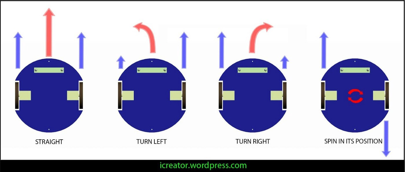
Diff Drive Controller
로봇 청소기와 같이 제자리 회전이 가능하며, 양쪽 바퀴 회전수 차이로 로봇을 이동시키는 타입을 DD Type이라고 부릅니다. 일전 fusionbot이 여기에 해당합니다. 이 모델이 하도 많이 사용되어서 그런지 gazebo_ros 차원에서 plugin을 제공하고 있습니다.
- 예시 실행 전 plugin 적용을 위해 fusionbot_description/urdf/fusionbot.urdf.xacro 파일에서 line 5, include line 주석을 해제합니다.
<?xml version="1.0"?>
<robot name="fusionbot" xmlns:xacro="http://www.ros.org/wiki/xacro">

  <xacro:include filename="$(find fusionbot_description)/urdf/materials.xacro" />
  <xacro:include filename="$(find fusionbot_description)/urdf/fusionbot.gazebo" />
- 수정, 저장 후 예시를 다시 실행해봅시다.
ros2 launch fusionbot_description gz.launch.py
- dd controller plugin이 제공하는 topic들을 확인해봅시다.
$ ros2 topic list
/clock
/cmd_vel
/front_camera/camera_info
/front_camera/image_raw
/joint_states
/odom
/parameter_events
/performance_metrics
/robot_description
/rosout
/scan
/tf
/tf_static
| Topic Name | Description |
|---|---|
| /cmd_vel | 로봇 제어를 위한 topic으로 geometry_msgs/msg/Twist 타입을 갖습니다. |
| /odom | 로봇의 위치와 속도, 방향을 모두 포함하는 odometry data topic 입니다. |
| /tf | tf2 data로 odom 및 fixed tf2들이 publish 됩니다. |
| /joint_states | 로봇 바퀴가 굴러감에 따라 변화하는 joint angle들을 publish 합니다. |
- rqt_robot_steering을 통해 로봇을 제어해봅시다.
rqt_robot_steering
⇒ 일전 껍데기에 불과했던 fusionbot이 어떻게 제어될 수 있었는지 과정을 설명해보겠습니다.
- urdf 폴더에 2가지 plugin을 추가하고, 매개변수를 맞춰줍니다.
<?xml version="1.0" ?>
<robot name="fusionbot" xmlns:xacro="http://www.ros.org/wiki/xacro" >

<gazebo>
  <plugin name='fusionbot_joint_state' filename='libgazebo_ros_joint_state_publisher.so'>
    <ros>
      <remapping>~/out:=joint_states</remapping>
    </ros>
    <update_rate>30</update_rate>
    <joint_name>right_wheel_joint</joint_name>
    <joint_name>left_wheel_joint</joint_name>
  </plugin>
</gazebo>

<gazebo>
  <plugin name='differential_drive_controller' filename='libgazebo_ros_diff_drive.so'>
    <update_rate>30</update_rate>
    <left_joint>left_wheel_joint</left_joint>
    <right_joint>right_wheel_joint</right_joint>
    <wheel_separation>0.2</wheel_separation>
    <wheel_diameter>0.1</wheel_diameter>
    <max_wheel_torque>50</max_wheel_torque>
    <max_wheel_acceleration>1.0</max_wheel_acceleration>
    <command_topic>cmd_vel</command_topic>
    <publish_odom>1</publish_odom>
    <publish_odom_tf>1</publish_odom_tf>
    <publish_wheel_tf>0</publish_wheel_tf>
    <odometry_topic>odom</odometry_topic>
    <odometry_frame>odom</odometry_frame>
    <robot_base_frame>base_footprint</robot_base_frame>
  </plugin>
</gazebo>

</robot>
- libgazebo_ros_joint_state_publisher
| Description | |
|---|---|
| remapping | ?? data type을 갖는 joint state topic 이름을 remapping 합니다. |
| update_rate | joint state topic의 publish rate |
| joint_name | tracking할 joint들이며 DD robot은 좌-우 2개가 될 것입니다. |
- libgazebo_ros_diff_drive
| Description | |
|---|---|
| update_rate | state topic publish rate |
| left_joint, right_joint | DD type 로봇 URDF에서 좌-우 joint를 적어줍니다. |
| wheel_separation | 좌-우 바퀴 사이의 거리 |
| wheel_diameter | 바퀴의 지름 |
| max_“value” | 제어와 관련된 물성치입니다. 정확하게 하고 싶다면 실제 모터 스펙을 통해 맞춰줍니다. |
| command_topic | Twist type을 갖는 로봇 제어 topic으로, 기본값은 cmd_vel입니다. |
| publish_odom | odometry topic의 publish 여부 |
| publish_odom_tf | odometry tf2의 broadcast 여부 (topic과 tf2는 다른 개념입니다!) |
| publish_wheel_tf | 양쪽 바퀴의 tf2 publish 여부 |
| odometry_topic | odometry topic name |
| odometry_frame | odometry tf2 broadcast 시 사용될 이름 |
| robot_base_frame | 로봇 tf2가 시작되는 기준 frame |
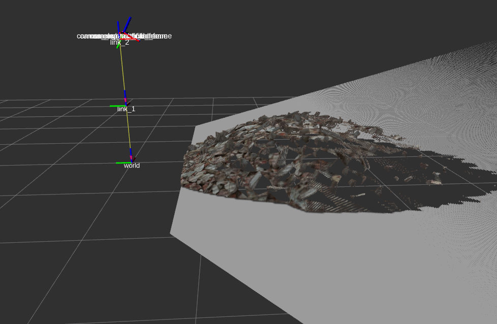
- rviz2를 통해 odometry topic을 시각화해봅시다.
Differential Drive Type은 Gazebo에서 기본 제공하지만, 이는 gazebo_ros가 만들어지기 전, Gazebo 개발자들이 로봇 예시를 위해 만들어둔 것일 뿐입니다. 따라서 좀 더 모던한 ros2_control 사용을 권장합니다.
Gazebo State Plugin
- 일전 tf2 예시에서 사용되었던, 마치 행성과 위성 같은 시뮬레이션 기억하시나요?
ros2 launch tf2_world tf2_world.launch.py
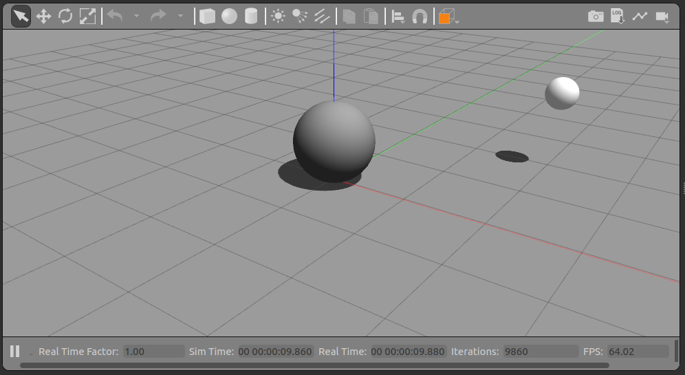
- 이 예시에서 gazebo_ros의 기본 topic을 통해 매우 정확한 위치 데이터를 사용하였습니다.
$ ros2 topic list
/clock
/link_states
/model_states
/parameter_events
/performance_metrics
/rosout
- 이러한 topic들을 사용하고 싶다면, gazebo world file에 libgazebo_ros_state plugin을 추가하면 됩니다.
Multi Object Spawning
여러대의 로봇, 여러개의 동일한 센서를 시뮬레이션하고 싶은 경우를 다뤄봅시다.
- 준비된 예시의 역분석을 통해 학습해보고자 합니다. 우선 예시를 실행해봅시다.
ros2 launch chess_world chess_world.launch.py
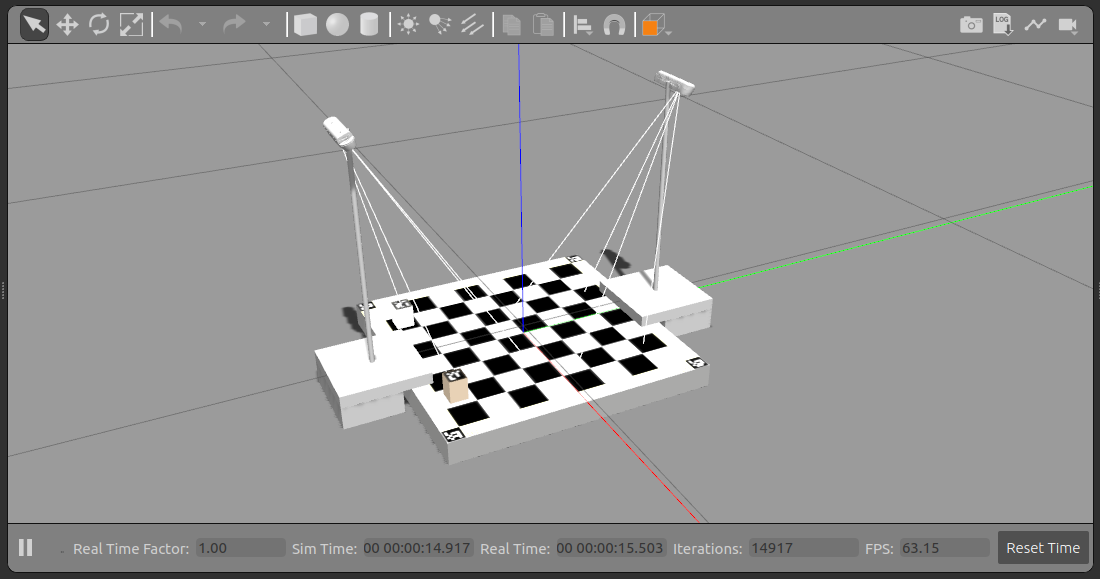
체스보드 양쪽으로 동일한 realsense camera가 등장한 것을 볼 수 있습니다.
- 이 예시를 역으르 해석해가면서 multi object 상황에 대한 gazebo환경에 대해 학습해보겠습니다.
- launch file 분석
- urdf 분석
- gazebo plugin 분석
- launch file 분석 - chess_world.launch.py
cam1_spawn = robot_spawn_nodes(0, "camera_left.urdf.xacro", pkg_path)
cam2_spawn = robot_spawn_nodes(1, "camera_right.urdf.xacro", pkg_path)

return LaunchDescription(
    [
        arg_show_rviz,
        start_gazebo_server_cmd,
        start_gazebo_client_cmd,
        static_transform_publisher,
        *cam1_spawn,
        *cam2_spawn,
        rviz_node,
    ]
)
⇒ 하나의 object 시뮬레이션을 위해 필요한 node들을 묶어 함수화하고, 이를 통해 cam1_spawn, cam2_spawn을 만들었습니다.
- 다시 robot_spawn_nodes 함수를 살펴봅시다.
return [
    robot_state_publisher,
    spawn_entity,
]
서로 다른 urdf file을 사용하기 때문에 robot_state_publisher가, 로봇을 등장시키는 과정이 반복되어야 하기 때문에 spawn_entity가 포함되어 있습니다.
- 사용할 xacro file과 spawn 위치를 매개변수로 받아 실행되는 구조입니다. 더욱이, 여기서 주목해야 할 점은 namespace를 사용하였다는 점입니다.
def robot_spawn_nodes(id, xacro_name, pkg_path):
    # Get URDF via xacro
    robot_description_content = Command(
        [
            PathJoinSubstitution([FindExecutable(name="xacro")]),
            " ",
            PathJoinSubstitution(
                [FindPackageShare("chess_world"), "urdf", xacro_name]
            ),
        ]
    )

    robot_description = {"robot_description": robot_description_content}
    ...
    # Spawn Robot
    spawn_entity = Node(
        package='gazebo_ros',
        executable='spawn_entity.py',
        namespace=f'camera_{id}',
        arguments=[
            '-topic', 'robot_description',
            '-entity', f'd435_camera_{id}',
            '-x', str(0),
            '-y', str(0.0),
            '-Y', str(0.0),
        ],
        output='screen'
    )
- camera_right.urdf.xacro & camera_left.urdf.xacro
⇒ 링크를 통해 이 둘을 비교해봅시다. ⇒ camera_right.urdf.xacro / camera_left.urdf.xacro
⇒ 반복되는 구문을 함수화하고, 기능상의 on/off를 변수화하여 별도 관리하고 있습니다. xacro의 사용이 아주 빛나는 상황입니다.
<?xml version="1.0"?>
<robot xmlns:xacro="http://ros.org/wiki/xacro" name="camera_<>">

  <xacro:include filename="$(find chess_world)/urdf/sensors/_d415.urdf.xacro"/>
  <xacro:include filename="$(find chess_world)/urdf/sensors/cam_holder.urdf.xacro"/>

  <link name="chess_frame" />

  <!-- sets camera frame w.r.t. to chess frame-->
  <!-- set only the color camera and a slow frame rate - an image each 5 seconds)-->
  <xacro:sensor_d415 name="camera_<>" parent="chess_frame" flag_color="1" flag_ir="0" flag_depth="0" updaterate="10">
    <origin xyz="? ? ?" rpy="? ? ?" />
  </xacro:sensor_d415>
  <!-- result from calib -->

  <!-- sets cam holder w.r.t to camera-->
  <xacro:cam_holder name="camera_<>_holder" parent="camera_<>_link">
    <origin xyz="0.0 -0.020 0.0115" rpy="0 -1.161379 0" />
  </xacro:cam_holder>
</robot>
- 각각의 xacro file내에는 변화하는 부분을 변수로 두어 상위 xacro에서 매개변수를 전달하기만 하면 언제든 독립된 모델을 만들 수 있도록 설계되었습니다.
<?xml version="1.0"?>
<robot name="cam_holder" xmlns:xacro="http://ros.org/wiki/xacro">
<xacro:macro name="cam_holder" params="name parent *origin">

...

<robot name="sensor_d415" xmlns:xacro="http://ros.org/wiki/xacro">
<xacro:macro name="sensor_d415" params="name parent flag_color flag_ir flag_depth updaterate *origin">
⇒ 이러한 이유에서 xacro의 사용이 권장됩니다.
- 실제 에시를 실행하여 topic list를 조회해보아도 겹치는 이름 없이 잘 실행되는 모습을 확인 가능합니다.
$ ros2 topic list
/camera_0/joint_states
/camera_0/robot_description
/camera_1/joint_states
/camera_1/robot_description
/camera_left/color/camera_info
/camera_left/color/image_raw
/camera_right/color/camera_info
/camera_right/color/image_raw
/clicked_point
/clock
/goal_pose
/initialpose
/parameter_events
/performance_metrics
/rosout
/tf
/tf_static
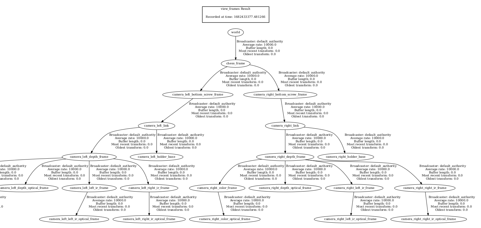
- 더욱이 tf2 tree도 완벽하게 구성되어 rviz2에서의 시각화도 문제없습니다.
다른 World 가져와서 써보기
이번에는, 오픈소스 프로젝트를 활용하여 나만의 world를 만드는 방법에 대해 학습해보겠습니다.
- 예시 실행
$ ros2 launch lidar_world lidar_world.launch.py
⇒ 해당 world는 제가 youtube 검색을 통해 괜찮다고 생각되어 직접 수정해본 것입니다. (물론 라이센스는 지켜야 합니다.) youtube link
- youtube link를 통해 접근할 수 있는 해당 프로젝트 코드를 분석해봅시다.
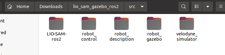
⇒ 사용된 패키지는 총 5개 입니다. 이들 중 gazebo와 관련이 깊을 것 같은 robot_gazebo 패키지에서 launch file을 분석합니다.
- robot_sim.launch.py
return LaunchDescription([
    IncludeLaunchDescription(
        PythonLaunchDescriptionSource(
            os.path.join(pkg_gazebo_ros, 'launch', 'gzserver.launch.py')
        ),
        launch_arguments={'world': world}.items(),
    ),

    IncludeLaunchDescription(
        PythonLaunchDescriptionSource(
            os.path.join(pkg_gazebo_ros, 'launch', 'gzclient.launch.py')
        ),
    ),

    IncludeLaunchDescription(
        PythonLaunchDescriptionSource(
            os.path.join(pkg_cart_pole_control, 'launch', 'robot_control.launch.py')
        ),
    ),

    IncludeLaunchDescription(
        PythonLaunchDescriptionSource([launch_file_dir, '/robot_state_publisher.launch.py']),
        launch_arguments={'use_sim_time': use_sim_time}.items(),
    ),

    Node(
    package = "joy",
    executable = "joy_node"
    ),
])
- 우리가 관심있는 것은 world file의 위치이며, 이렇게 찾은 lio_world.model을 gazebo_ros가 아닌 일반 Gazebo로 로컬 실행시켜봅니다.
gazebo lio_world.model
⇒ 아마 실행되지 않을 것입니다. lio_world.model에서는 gazebo 기본 model이 아닌 커스텀 모델들이 사용되고 있는데, 이들을 Gazebo 환경변수에 추가해주어야 하기 때문입니다.
- 따라서 나만의 패키지를 구성하고, 이 world를 다시 실행시켜봅니다.
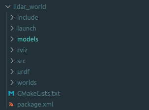
- 패키지 생성
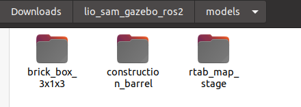
- launch file 생성, world file, models file 복사
- CMakeLists.txt 수정
- 패키지 빌드 후, 실행
이전에 배운 sensor plugin, urdf, sensor stick, moving stick을 모두 활용해서 여러분만의 camera & lidar world를 만들어 보세요!! - 과제입니다.
⇒ 제가 만든 World를 참고하셔도 좋지만 직접 해보시기를 권장드립니다.
⇒ object animation은 다음 링크를 참고합니다. link